What is the purpose of a fluidized bed dryer schematic diagram?
What Is a Fluidized Bed Dryer Diagram?
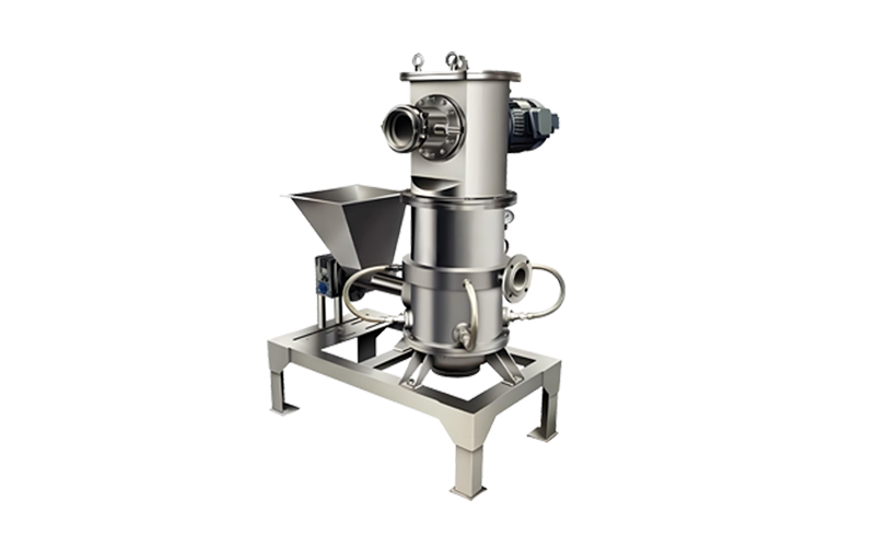
A Fluidized Bed Dryer Diagram illustrates the internal layout of an industrial fluid bed drying system, focusing on airflow distribution, particle movement, and key functional zones.
Unlike marketing images, an engineering diagram is used to evaluate drying efficiency, pressure drop, scalability, and maintenance accessibility.
This type of diagram is widely referenced during process design, equipment comparison, and procurement evaluation, especially in pharmaceutical, chemical, and food powder applications.
Fluidized Bed Dryer Diagram – Main Components and Functions
Air Distribution System (Air Distribution Plate Design)
The air distribution plate is the most critical element shown in a fluidized bed dryer diagram.
Ensures uniform airflow across the bed surface
Prevents channeling and localized overheating
Determines minimum fluidization velocity

Fluidization and Drying Chamber
In the fluidization zone, particles are suspended and mixed by upward hot air flow.
Key engineering characteristics shown in the diagram include:
Bed expansion height
Chamber geometry
Gas–solid contact path
These parameters directly affect moisture removal rate and drying uniformity, particularly for heat-sensitive powders.
Exhaust Air and Filtration Section
A complete fluidized bed dryer diagram clearly indicates the exhaust and dust separation system.
Typical features include:
Bag filter or cartridge filter housing
Fine powder recovery design
Protection of downstream fan and ducting
From an operational standpoint, this section determines material loss, cleaning frequency, and compliance with emission standards.
Why Engineers Rely on Fluidized Bed Dryer Diagrams
For process engineers, the diagram provides insight beyond datasheets:
Evaluation of airflow balance
Identification of potential agglomeration zones
Assessment of scalability from pilot to production
In technical reviews, diagrams are often used to validate whether a dryer design can maintain stable fluidization under variable load conditions.
Procurement Value of a Detailed Fluidized Bed Dryer Diagram
From a procurement perspective, a well-defined diagram helps clarify:
Actual scope of supply
Material contact areas and construction standards
Maintenance access and downtime risk
Clear diagrams reduce misunderstandings during bidding, FAT, and commissioning stages.
Fluidized Bed Dryer Diagram vs Other Dryer Designs
Compared with rotary dryers or tray dryers, a fluidized bed dryer diagram highlights:
No internal mechanical mixing components
Compact vertical layout
High heat and mass transfer efficiency
These features explain its preference for continuous, automated powder drying processes.
Engineering Summary
A Fluidized Bed Dryer Diagram is a technical decision tool.
It reflects real airflow behavior, drying performance, and long-term operational reliability.
For engineers, it ensures process stability.
For buyers, it reveals the true value behind quoted specifications.
Understanding the diagram is essential for selecting a fluid bed dryer that performs reliably in industrial production.

https://www.linkedin.com/in/loreene-qi-b5b0a7165/
Email: [email protected]
Whatsapp: +8618717883822